
Netcode Client Architecture
The "Client General" UML diagram illustrates Netcode client-side architecture with related entities (classes, interfaces, structures). This is a high-level wrapper for FishNet open-source solution.
1. Overview
The idea to have client-authoritive flexible design that allows: scale kind/size of data without changes on server-side, keep Netcode code clean from concrete implementations, have different type of data independent of from each other when transfer and have a maximum control over data that system transfers.
2. Intro
Diagram uses UML standarts to show data flows, dependencies between entities and general contracts. Diagram has few groups of blocks:
- Core (top part: ICLient, Receive/SendHandler, MessageQueue and IEvents).
- FishNet and Valusocial (left part: FishNet.ClientManager, FishNetMessage, ValusocialHubManager etc).
- Receivers and Senders (center part: IReceiver, ISender, IEventsReceiver etc).
- Transform (bottom right part: example of Receiver and Sender to sync object position and rotation)
- Emotion (bottom left part: example of IEventReceiver to broadcast avatar emotions/reactions)
3. Flows
3.1 Bootstrap
- The process begins when a ClientConnected event occurs, signaling that a new client has joined the network. At this point, a
ClientDataobject is created, containing essential information such as the client’s uniqueId, ownership flag (IsOwner), and a reference to theIClientinterface. This data is then used to instantiate aClientPrefab, representing the runtime instance of the connected user within the system. - Once the prefab is instantiated, it moves to the initialization phase, where two key network components — NetworkTransform and NetworkEmotions — are initialized.
- NetworkTransform handles positional and rotational updates across the network via serialized messages.
- NetworkEmotions manages event-based emotion synchronization, allowing real-time expressive communication between clients.
- After initialization, both components are registered with the
IClientinterface, which completes the setup. The client is now fully integrated into the session and capable of sending and receiving network updates.
Overall, the sequence follows three main stages:
- Instantiate — Create and configure the client’s prefab instance.
- Initialize — Set up core communication modules for transform and emotion synchronization.
- Register — Bind modules to the
IClientsystem for network participation.
This ensures each new client becomes a synchronized, event-aware participant in the connected environment.
3.2 Push Flow
- The process begins with the NetworkTransform component, which continuously fetches local transform updates — including position and rotation — and prepares them for network transmission. These updates are encapsulated into a
TransformMessagestructure that holds the serialized state of the client’s transform. - The
TransformMessageis then passed to the SendHandler, where it is converted and pushed into a message format suitable for network communication. TheSendHandlertransforms the message into aMessageTypeandbyte[]payload, ensuring it can be interpreted consistently across different clients. - Next, the serialized data flows through the IClient interface, which handles message batching and dispatch preparation. Here, multiple messages of the same type are grouped together by
MessageTypeto reduce network overhead and optimize transmission. - Finally, the batched data is passed to the FishNet.ClientManager, which performs the broadcast operation. Messages are batched and sent every 100 milliseconds, ensuring regular and efficient synchronization of transform data across all connected peers.
In summary, the sequence covers three major stages:
- Fetch & Push — NetworkTransform gathers transform changes and encapsulates them in
TransformMessage. - Convert & Prepare — SendHandler and IClient serialize and batch messages by type.
- Broadcast — FishNet.ClientManager sends aggregated updates at fixed intervals (100ms).
This design ensures efficient, low-latency transform synchronization across networked clients while minimizing bandwidth usage through intelligent batching and timed dispatch.
3.3 Receive Flow
- The process begins with the FishNet.ClientManager, which acts as the primary entry point for network communication. It continuously listens for incoming FishNetMessage packets from other clients or the server. When a message arrives, it is passed to the IClient interface for processing.
- Within IClient, the raw
FishNetMessageis converted and received as a byte stream (byte[]). TheIClientacts as a bridge that translates the network protocol data into a form that can be handled by the client-side components. - Next, the byte array is forwarded to the ReceiveHandler, which performs deserialization and reconstructs the data into a strongly typed
TransformMessage. This message contains the updated positional and rotational data that needs to be applied to the client’s networked entities. - Finally, the NetworkTransform component consumes the
TransformMessage, processing and applying the received updates to synchronize the local representation of the entity with the remote state. This ensures all clients maintain a consistent spatial view across the network.
In summary, the sequence follows three main stages:
- Receive — FishNet.ClientManager collects incoming network packets.
- Convert & Deserialize — IClient and ReceiveHandler convert byte data into structured messages.
- Process & Apply — NetworkTransform updates the local entity’s transform based on received data.
This receive pipeline provides a reliable and efficient mechanism for keeping all clients synchronized in real-time through consistent message handling and transform application.
4. Hubs
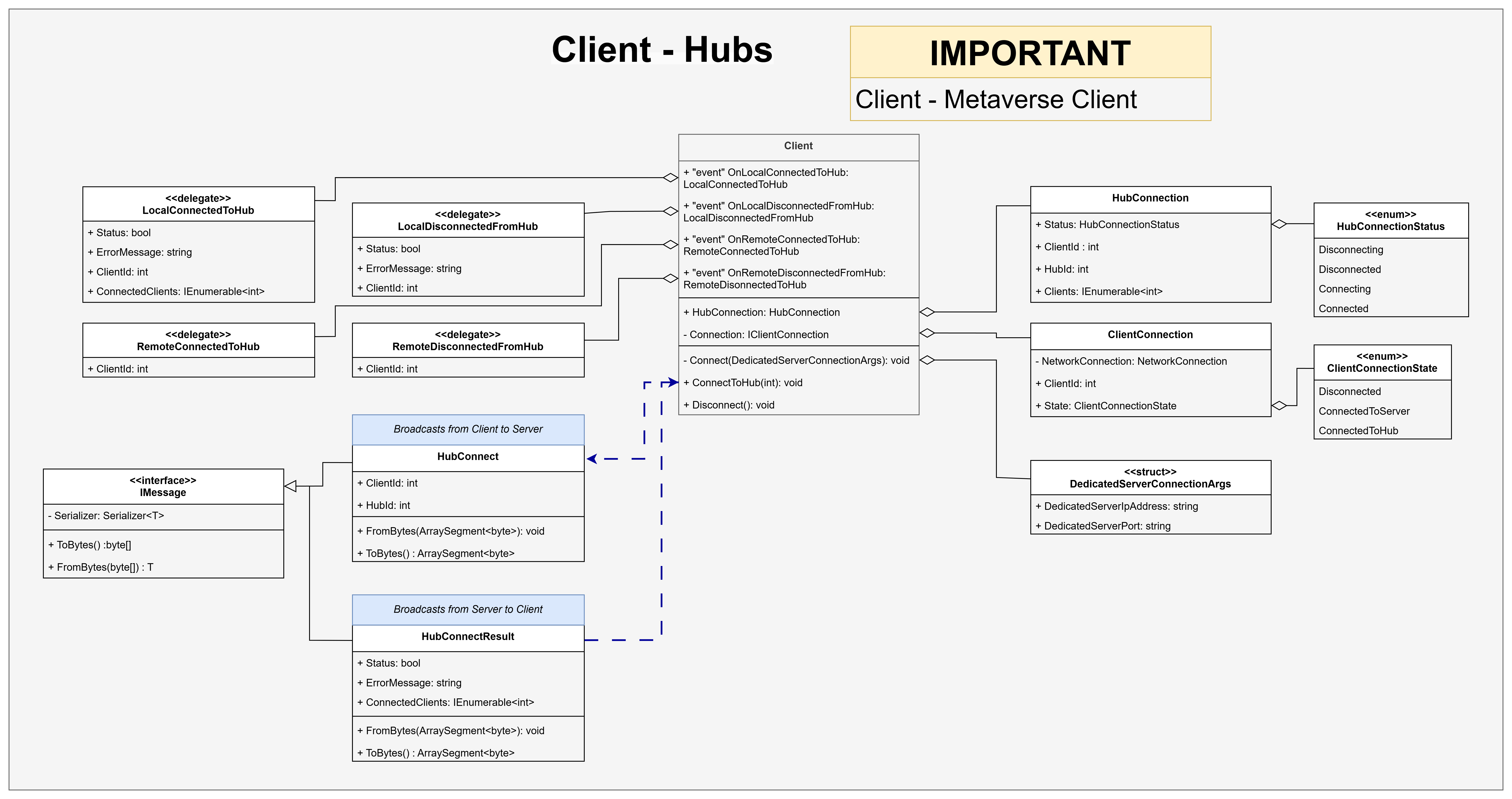
4.1 Overview
Each Client manages hub connections through events, message exchanges, and status tracking.
It maintains a HubConnection for hub state and a ClientConnection for the low-level network link, using delegates to handle connection and disconnection events.
4.2 Core Components
Client — Coordinates all hub-related actions.
- Methods:
Connect(),ConnectToHub(), andDisconnect(). - Events:
LocalConnectedToHub/LocalDisconnectedFromHubRemoteConnectedToHub/RemoteDisconnectedFromHub
- Methods:
HubConnection — Tracks current connection details:
Status,ClientId,HubId, and connected clients.ClientConnection — Manages direct network state (
ClientConnectionState).DedicatedServerConnectionArgs — Contains the server’s address and port for connection setup.
4.3 Message Flow
Hub communication uses two main messages:
HubConnect (Client → Server)
ContainsClientIdandHubId, serialized via theIMessageinterface.HubConnectResult (Server → Client)
ReturnsStatus,ErrorMessage, and the list of connected clients.
Both implement standardized ToBytes() and FromBytes() methods for reliable serialization.
4.4 Connection States
- HubConnectionStatus:
Disconnecting,Disconnected,Connecting,Connected - ClientConnectionState:
Disconnected,ConnectedToServer,ConnectedToHub
These ensure deterministic synchronization between local and remote peers.
4.5 Workflow Summary
- Client calls
ConnectToHub(). - Sends a
HubConnectmessage to the server. - Receives a
HubConnectResultconfirming status. - Triggers connection events (
LocalConnectedToHub, etc.). - Updates
HubConnectionandClientConnectionstates.
This event-driven structure provides consistent and scalable hub management across all connected clients.